
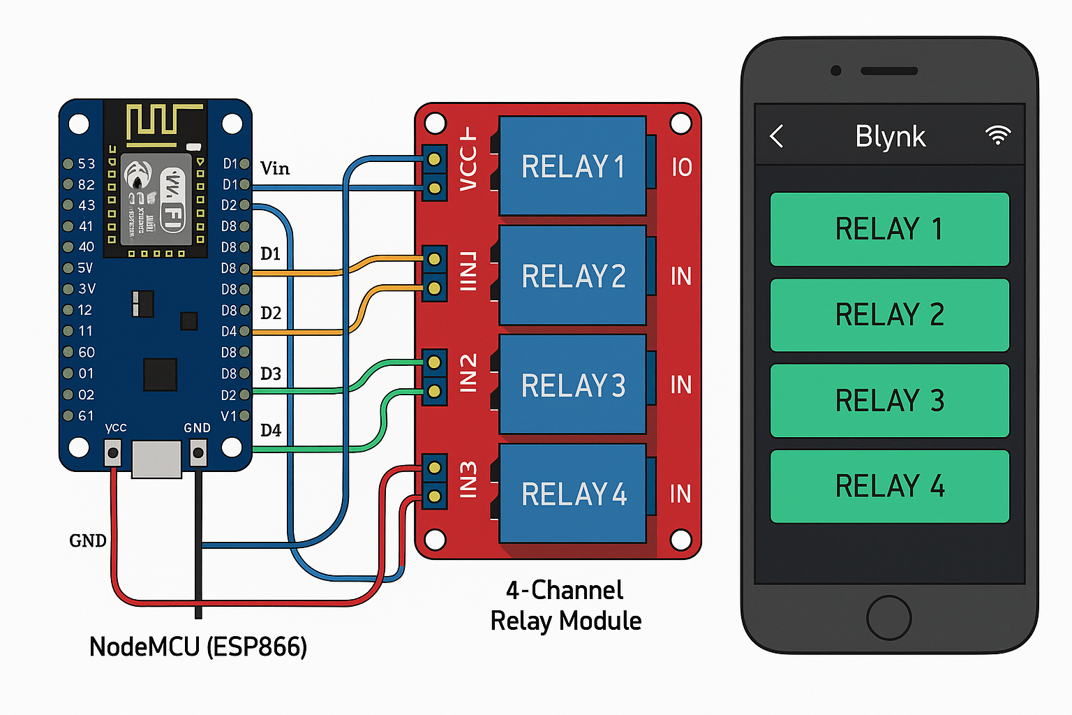
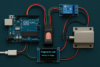
Controlling 4 relays using a NodeMCU (ESP8266) via Wi-Fi and the Blynk app is a great way to build an IoT home automation project. Below is a step-by-step guide, including the circuit diagram, Blynk setup, and Arduino code.
🧰 Requirements
- NodeMCU (ESP8266)
- 4-channel Relay Module
- Blynk IoT App (on iOS/Android)
- Jumper Wires
- Power Supply (5V for relays, 3.3V logic for NodeMCU)
📲 Blynk App Setup
- Install Blynk IoT app (new version, not legacy).
- Create a New Project.
- Add 4 buttons (set each to “Switch” mode).
- Assign them to Virtual Pins V0, V1, V2, V3.
- Note your Auth Token, or set up Blynk with template credentials.
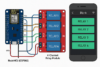
NodeMCU        Relay Module
D1 (GPIO5)  -> IN1
D2 (GPIO4)  -> IN2
D3 (GPIO0)  -> IN3
D4 (GPIO2)  -> IN4
GND         -> GND
Vin (5V)    -> VCC (use external 5V if needed)
💻 Arduino Code
First, install the following libraries via Library Manager:
- Blynk (latest)
- ESP8266WiFi
Here’s a detailed explanation of how the NodeMCU (ESP8266), relay module, and Blynk app work together to control 4 relays:
🔁 Overall System Workflow
- Blynk App (Mobile) → Sends virtual pin commands via Wi-Fi
- Blynk Cloud Server → Transfers the virtual pin states to NodeMCU
- NodeMCU (ESP8266) → Reads the states and controls the relays
- Relay Module → Switches electrical devices ON/OFF
🔧 Component Breakdown
🧠 1. NodeMCU (ESP8266)
- A microcontroller with built-in Wi-Fi.
- Connects to your Wi-Fi network and communicates with Blynk Cloud.
- Uses GPIO pins to send signals to the relay module.
- Each relay is controlled using a digital output pin (D1 to D4).
📱 2. Blynk App
- Acts as a remote control interface.
- You add buttons in the app and link them to virtual pins (V0 to V3).
- When you tap a button, Blynk sends the signal via the internet to the NodeMCU.
Example:
- Tap “Relay 1 ON” → App sets
V0 = 1→ Blynk Cloud → NodeMCU receivesV0 = 1
☁️ 3. Blynk Cloud Server
- Middleware that handles communication between the app and your NodeMCU.
- Keeps your device and app synchronized, even when they’re on different networks.
- Your NodeMCU uses
Blynk.run()in theloop()to constantly check for incoming messages.
⚡ 4. Relay Module
- A relay is an electromechanical switch.
- It has 3 pins: IN, VCC, and GND.
- IN pin is connected to a NodeMCU GPIO. When the GPIO goes LOW, the relay activates.
- It switches a higher-power circuit (like 220V light or fan) safely.
Most relay modules are active LOW, which means:
- LOW signal (0V) → Turns relay ON
- HIGH signal (3.3V) → Turns relay OFF
🔌 Power and Safety Notes
- NodeMCU operates at 3.3V logic.
- Relay module typically requires 5V VCC and uses optocouplers to isolate high-voltage devices.
- Use an external 5V power supply if you’re switching high-power loads.
- Always share GND between NodeMCU and the relay module.
🧪 How It All Comes Together
- Power on the NodeMCU and relay module.
- NodeMCU connects to your Wi-Fi and logs in to Blynk Cloud using your Auth Token.
- The app initializes with buttons linked to virtual pins.
- Pressing a button on the app:
- Sends a
1(ON) or0(OFF) to the virtual pin. - The
BLYNK_WRITE(Vx)function in the code receives this signal. - The function uses
digitalWrite()to toggle the respective GPIO pin. - The GPIO pin goes LOW or HIGH, activating or deactivating the relay.
- Sends a
📊 Example: What happens when you press “RELAY 2” button:
- Button linked to V1.
- Press ON → App sends
1toV1. - NodeMCU receives it and executes:
BLYNK_WRITE(V1) { digitalWrite(RELAY2, param.asInt() ? LOW : HIGH); }LOWsignal is sent to D2 (RELAY2).- Relay2 switches ON.
- Light/Fan connected to that relay turns ON.
#define BLYNK_TEMPLATE_ID "YourTemplateID"
#define BLYNK_TEMPLATE_NAME "RelayControl"
#define BLYNK_AUTH_TOKEN "YourAuthToken"

#include <ESP8266WiFi.h>
#include <BlynkSimpleEsp8266.h>

// Replace with your network credentials
char ssid[] = "YourWiFiSSID";
char pass[] = "YourWiFiPassword";

// Define relay pins
#define RELAY1 D1  // GPIO5
#define RELAY2 D2  // GPIO4
#define RELAY3 D3  // GPIO0
#define RELAY4 D4  // GPIO2

void setup()
{
  // Debug console
  Serial.begin(9600);

  Blynk.begin(BLYNK_AUTH_TOKEN, ssid, pass);

  // Set relay pins as outputs
  pinMode(RELAY1, OUTPUT);
  pinMode(RELAY2, OUTPUT);
  pinMode(RELAY3, OUTPUT);
  pinMode(RELAY4, OUTPUT);

  // Initialize all relays off
  digitalWrite(RELAY1, HIGH); // Active LOW
  digitalWrite(RELAY2, HIGH);
  digitalWrite(RELAY3, HIGH);
  digitalWrite(RELAY4, HIGH);
}

// Blynk virtual pin handlers
BLYNK_WRITE(V0) {
  digitalWrite(RELAY1, param.asInt() ? LOW : HIGH);
}
BLYNK_WRITE(V1) {
  digitalWrite(RELAY2, param.asInt() ? LOW : HIGH);
}
BLYNK_WRITE(V2) {
  digitalWrite(RELAY3, param.asInt() ? LOW : HIGH);
}
BLYNK_WRITE(V3) {
  digitalWrite(RELAY4, param.asInt() ? LOW : HIGH);
}

void loop()
{
  Blynk.run();
}
🧪 Testing
- Upload the code via Arduino IDE to the NodeMCU.
- Open the Blynk app and press the buttons.
- Each button should toggle one relay.
🛠️ Tips
- Relays are active LOW, meaning
LOWturns them ON. - Debounce logic is not needed as Blynk manages state.
- Secure your Wi-Fi and consider using Blynk cloud templates for better project management.
✅ Conclusion
Controlling 4 relays with a NodeMCU (ESP8266) and the Blynk app offers a flexible, wireless home automation solution. Here’s what we’ve achieved:
- ✅ Built a Wi-Fi-connected remote relay controller using NodeMCU
- ✅ Used the Blynk IoT app to toggle devices via virtual pins
- ✅ Interfaced with a 4-channel relay module to switch real-world appliances
- ✅ Ensured safe and effective control with simple code and circuit
This setup can be used to control:
- Lights
- Fans
- Garage doors
- Water pumps
- And more — all remotely from your phone
🔧 Want to expand further? You can:
- Add voice assistants (Alexa, Google Home)
- Use Blynk Automations (e.g., timer, geolocation)
- Integrate sensor feedback (temperature, motion, etc.)


