

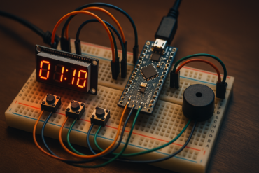
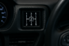
I have a small hatchback car with manual transmission and I often think to display current gear in the dashboard instrument panel, So I decided to make something fancy, In this tutorial we are going to build a car gear position indicator for a manual transmission (H-pattern) with 5 forward gears + 1 reverse using:
- Arduino Nano
- 6 Limit Switches (for gear detection)
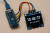
- 0.96″ I2C OLED Display (typically SSD1306, 128×64)
⚙️ System Overview
Each gear position has a dedicated limit switch:
- Gear 1 → Switch 1
- Gear 2 → Switch 2
- …
- Gear R (reverse) → Switch 6
You’ll read these switches as digital inputs and display the active gear on the OLED.
🧰 Components Needed
- Arduino Nano
- SSD1306 OLED (I2C)
- 6x Limit Switches
- Pull-down resistors (or use internal pull-ups and wire switches to ground)
- Jumper wires, breadboard or PCB
⚙️ Concept: H-Pattern Manual Transmission Gear Indicator
Goal: Display a visually clear and attractive H-pattern gear layout with real-time gear selection based on limit switch input.
🧩 Components Breakdown
| Component | Purpose |
|---|---|
| Arduino Nano | Reads gear position from limit switches |
| 6 Limit Switches | One per gear (1–5 + R), mounted to shifter |
| OLED Display | Shows the H-pattern layout with gear labels |
| Graphics (OLED or Simulation) | Visual representation of gear state |
🖥️ OLED Wiring (I2C)
| OLED Pin | Arduino Nano Pin |
|---|---|
| VCC | 5V |
| GND | GND |
| SDA | A4 |
| SCL | A5 |
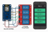
🔌 Limit Switch Wiring Example
Wire one side of each limit switch to GND, the other side to a digital pin (D2–D7 for example). Enable internal pull-up resistors in code.
🛠️ Notes
- When no gear is engaged, all switches are unpressed → system shows “N” (Neutral).
- You can improve it by debouncing the switch inputs if needed.
- Mount the switches such that only one is pressed at a time.
- If 2 or more are pressed (like during shift), you can prioritize or show “Shifting”.
🔲 OLED Gear Layout Example (H Pattern)
1   3   5
|   |   |
2   4   R
We’ll draw all gears statically, and dynamically highlight the active gear by inverting its number (or drawing a box around it).
🧾 Arduino Code – H Pattern Gear Display with Highlight
Ensure you have these libraries installed:
#include <Wire.h>
#include <Adafruit_GFX.h>
#include <Adafruit_SSD1306.h>
🔧 Customization Tips
- You can adjust
gearXandgearYvalues to better fit your screen or layout. - Add connecting lines between gears if desired (like drawing vertical/horizontal lines for realism).
- Add an optional
"N"(Neutral) box if no gear is pressed.
✅ Features
- Full H-pattern layout
- Gear connections (lines)
- Highlighted active gear
- Optional Neutral display if no gear is selected
- Smooth and clean layout
🖥️ How It Works
1. Gear Detection via Limit Switches
Each gear position in your physical gear shifter presses a unique limit switch when selected.
- Limit switches are connected to digital pins on the Arduino Nano.
- Each switch is pulled HIGH via
INPUT_PULLUP. - When a gear is engaged, its switch goes LOW → Arduino detects it.
2. Gear Mapping Logic
In the Arduino sketch:
- We scan all switch inputs.
- The first detected LOW input tells us which gear is active.
- If no gear is active, we consider it Neutral.
3. OLED Display Update
Based on the active gear:
- A pre-drawn H-pattern is shown with all gear positions.
- The current gear is highlighted (by color inversion or glow effect).
- If no gear is pressed, a Neutral “N” is displayed.
🧾 Arduino Code upload by using Arduino IDE
#include <Wire.h>
#include <Adafruit_GFX.h>
#include <Adafruit_SSD1306.h>

#define SCREEN_WIDTH 128
#define SCREEN_HEIGHT 64

Adafruit_SSD1306 display(SCREEN_WIDTH, SCREEN_HEIGHT, &Wire, -1);

// Gear switch pins: 1 to 5 and Reverse
const int gearPins[6] = {2, 3, 4, 5, 6, 7};
const char* gearLabels[6] = {"1", "2", "3", "4", "5", "R"};

// Gear screen positions
const int gearX[6] = {10, 10, 50, 50, 90, 90}; // x-coords
const int gearY[6] = {0, 30, 0, 30, 0, 30};    // y-coords

int activeGear = -1;

void setup() {
  for (int i = 0; i < 6; i++) {
    pinMode(gearPins[i], INPUT_PULLUP);
  }

  if (!display.begin(SSD1306_SWITCHCAPVCC, 0x3C)) {
    while (true); // halt if OLED not found
  }

  display.clearDisplay();
  display.display();
}

void loop() {
  activeGear = -1;
  for (int i = 0; i < 6; i++) {
    if (digitalRead(gearPins[i]) == LOW) {
      activeGear = i;
      break;
    }
  }

  drawHPattern(activeGear);
  delay(100);
}

void drawHPattern(int highlight) {
  display.clearDisplay();

  // Draw vertical lines (gear gates)
  display.drawLine(18, 10, 18, 54, SSD1306_WHITE); // 1-2
  display.drawLine(58, 10, 58, 54, SSD1306_WHITE); // 3-4
  display.drawLine(98, 10, 98, 54, SSD1306_WHITE); // 5-R

  // Draw horizontal connectors
  display.drawLine(18, 20, 98, 20, SSD1306_WHITE); // upper line
  display.drawLine(18, 44, 98, 44, SSD1306_WHITE); // lower line

  // Draw gear numbers
  for (int i = 0; i < 6; i++) {
    int x = gearX[i];
    int y = gearY[i];

    if (i == highlight) {
      display.fillRect(x - 2, y - 2, 20, 18, SSD1306_WHITE);
      display.setTextColor(SSD1306_BLACK);
    } else {
      display.setTextColor(SSD1306_WHITE);
    }

    display.setTextSize(2);
    display.setCursor(x, y);
    display.print(gearLabels[i]);
  }

  // Optional: Show Neutral if no gear is selected
  if (highlight == -1) {
    display.setTextSize(2);
    display.setTextColor(SSD1306_WHITE);
    display.setCursor(40, 48);
    display.print("N");
  }

  display.display();
}
🧰 Notes
- You can change the line coordinates if your OLED is a different resolution.
- Works best with 128×64 OLEDs (SSD1306).
- All six gears are laid out in an accurate H-pattern.
- The highlighted gear gets inverted colors for visibility.
- If no switch is pressed, “N” (Neutral) is shown.
✅ Conclusion: Manual Transmission Gear Indicator with H-Pattern
You’ve now built a functional and visually enhanced gear position indicator for a manual transmission car using:
- Arduino Nano for logic and input reading
- Limit switches for real-time gear detection
- 0.96″ OLED display to show a classic H-pattern with highlighted gear feedback
This setup provides a clear, intuitive way to monitor gear selection on both physical and graphical interfaces. It’s especially useful for simulators, DIY dashboard projects, or driver training rigs.
🛠️ Suggested Improvements and Tips
1. Debounce Switch Inputs
Avoid gear flickering or false reads:
delay(20); // small debounce delay
Or implement proper software debouncing using millis().
2. Neutral Detection Enhancements
Currently, Neutral is when no gear is pressed. To improve:
- Add a dedicated “Neutral” switch
- Or detect the state where the stick is between gates
3. Add Sound or Haptic Feedback
- A small piezo buzzer for gear change tones
- Or vibrational feedback if you want tactile confirmation
4. Animated Transitions
Use frame-based drawing for smoother gear change animation:
- Slide highlight boxes
- Fade effects when switching gears
5. Backlit or Themed Displays
- Use color OLED (if available) for vibrant themes
- Customize gear highlight color (e.g., red for R, blue for normal gears)
6. Serial Output or Logging
- Send gear changes via
Serial.print()for debugging or telemetry logging - Integrate with an app or data logger
7. Upgrade Display for Advanced UI
- Use a TFT display (e.g., 1.8″ or 2.4″ SPI TFT) for full-color, richer graphics
- Integrate touchscreen to simulate automatic/manual mode switching
8. Encapsulate in a Dashboard Housing
Build a physical enclosure for the screen and gear detector:
- Use 3D printed or laser-cut dashboard panel
- Mount switches firmly under the shifter gate


