


Description
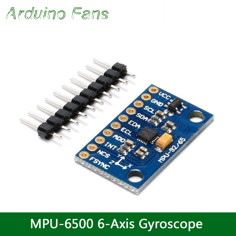
GY-9250 MPU-6500 MPU6500 Module 6 Axis analog gyro sensors+ 6 Axis Accelerometer Module Three dimensional Angle sensor for Arduino
- GY-9250 MPU-6500 MPU6500 Module
- 6 Axis analog gyro sensors
- 6 Axis Accelerometer
- 3-5v Power supply (internal low dropout regulator)
- Standard IIC communications protocol
- Chip built-in 16bit AD Converter, 16-bit Data Output
The InvenSense MPU-6500 sensor contains a MEMS accelerometer and a MEMS gyro in a single chip. It is very accurate, as it contains 16-bits analog to digital conversion hardware for each channel. Therefor it captures the x, y, and z channel at the same time. The sensor uses theI2C-bus to interface with the Arduino.
The MPU-6050 is not expensive, especially given the fact that it combines both an accelerometer and a gyro.
Features & Specifications
- Power supply :3-5v (internal low dropout regulator)
- Communication modes: standard IIC communications protocol
- Chip built-in 16bit AD converter, 16-bit data output
- Gyroscope range: ± 250 500 1000 2000 ° / s
- Acceleration range: ± 2 ± 4 ± 8 ± 16g
- Immersion Gold Board machine welding process to ensure quality
- Size: 20mm x 16mm (0.81 x 0.62 inch)
- Pin pitch 2.54mm
Reading the raw values for the accelerometer and gyro is easy. The sleep mode has to be disabled, and then the registers for the accelerometer and gyro can be read.
But the sensor also contains a 1024 byte FIFO buffer. The sensor values can be programmed to be placed in the FIFO buffer. And the buffer can be read by the Arduino.
The FIFO buffer is used together with the interrupt signal. If the MPU-6050 places data in the FIFO buffer, it signals the Arduino with the interrupt signal so the Arduino knows that there is data in the FIFO buffer waiting to be read.
A little more complicated is the ability to control a second I2C-device.
The MPU-6500 always acts as a slave to the Arduino with the SDA and SCL pins connected to theI2C-bus.
But beside the normal I2C-bus, it has it’s own I2C controller to be a master on a second (sub)-I2C-bus. It uses the pins AUX_DA and AUX_CL for that second (sub)-I2C-bus.
It can control, for example, a magnetometer. The values of the magnetometer can be passed on to the Arduino.
Things get really complex with the “DMP”.
The sensor has a “Digital Motion Processor” (DMP), also called a “Digital Motion Processing Unit”. This DMP can be programmed with firmware and is able to do complex calculations with the sensor values.
For this DMP, InvenSense has a discouragement policy, by not supplying enough information how to program the DMP. However, some have used reverse engineering to capture firmware.
The DMP (“Digital Motion Processor”) can do fast calculations directly on the chip. This reduces the load for the microcontroller (like the Arduino). The DMP is even able to do calculations with the sensor values of another chip, for example a magnetometer connected to the second (sub)-I2C-bus.
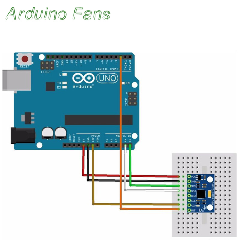
Arduino Interfacing Diagram
Additional information
| Weight | 50 g |
|---|---|
| Dimensions | 5 × 5 × 3 cm |
| Color | Blue |
| Power Supply | 5V DC |
Only logged in customers who have purchased this product may leave a review.
Tags
3 Axis Accelerometer, 3 Axis Gyro, Arduino, ESP32, ESP32S, ESP8266, GY-521, Module, MPU6050, NodeMCU, WeMos D1 MiniUPSELL PRODUCTS


RELATED PRODUCTS

LASTEST PRODUCTS
Products
-
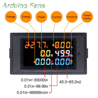
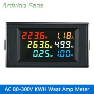 6 IN 1 80-300V AC Digital Voltmeter Ammeter 100A 4 Colors LCD Display
₨ 2,499
6 IN 1 80-300V AC Digital Voltmeter Ammeter 100A 4 Colors LCD Display
₨ 2,499
-
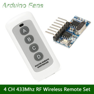
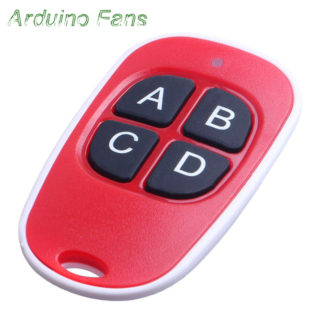
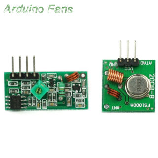
 4 Buttons 433MHz Universal 4 CH RF Wireless Remote Control Transmitter Receiver Set
₨ 719
4 Buttons 433MHz Universal 4 CH RF Wireless Remote Control Transmitter Receiver Set
₨ 719
-
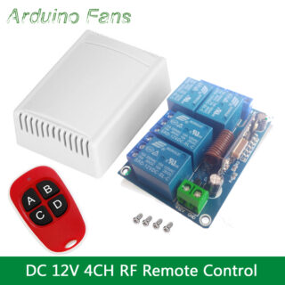
 Universal RF Wireless DC 12V 4 CH 433Mhz Remote Control Switch Relay Receiver Module With Remote Control For Smart Home
₨ 2,399
Universal RF Wireless DC 12V 4 CH 433Mhz Remote Control Switch Relay Receiver Module With Remote Control For Smart Home
₨ 2,399
-
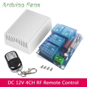 Universal DC 12V 4 CH 433Mhz RF Wireless Remote Control Switch Relay Receiver Module With Remote Control
₨ 2,449
Universal DC 12V 4 CH 433Mhz RF Wireless Remote Control Switch Relay Receiver Module With Remote Control
₨ 2,449
-
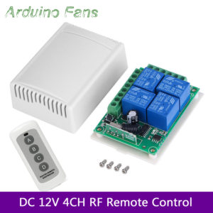 DC 12V 4 CH Universal 433Mhz RF Wireless Remote Control Switch Relay Receiver Module With Remote Control
₨ 2,399
DC 12V 4 CH Universal 433Mhz RF Wireless Remote Control Switch Relay Receiver Module With Remote Control
₨ 2,399
Top rated products
-
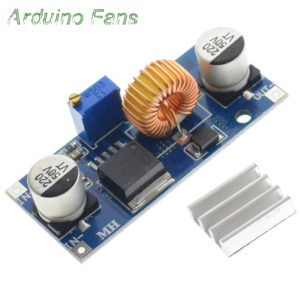 XL4015 5A DC-DC 4-38V to 1.25-36V Step Down Adjustable Power Supply Module
₨ 240
XL4015 5A DC-DC 4-38V to 1.25-36V Step Down Adjustable Power Supply Module
₨ 240
-
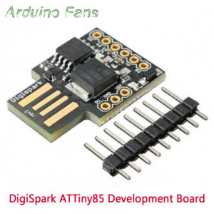 Digispark Kickstarter ATtiny85 USB Development Board Module For Arduino
₨ 699
Digispark Kickstarter ATtiny85 USB Development Board Module For Arduino
₨ 699
-
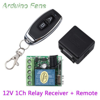
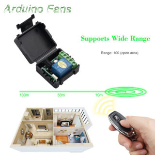
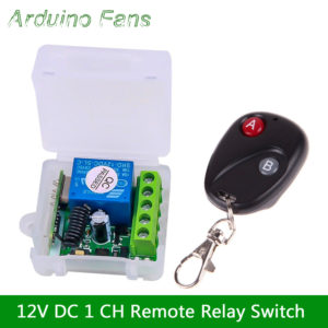 DC 12V 1CH Wireless Remote Control Switch 433Mhz Relay Receiver Module for Smart Home
₨ 849
DC 12V 1CH Wireless Remote Control Switch 433Mhz Relay Receiver Module for Smart Home
₨ 849
-
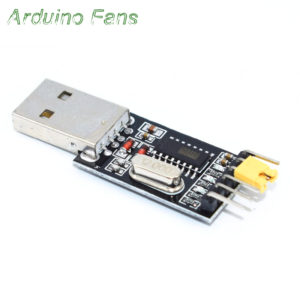 USB to TTL CH340G STC Microcontroller Board USB to Serial RS232 Converter
₨ 180
USB to TTL CH340G STC Microcontroller Board USB to Serial RS232 Converter
₨ 180
-
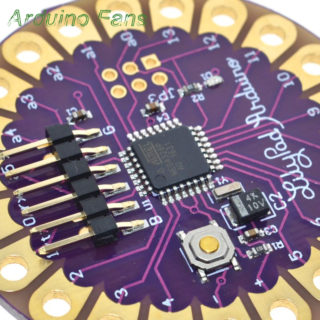
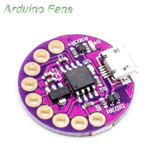
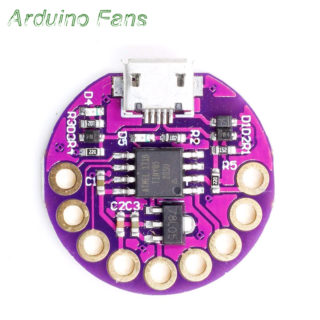
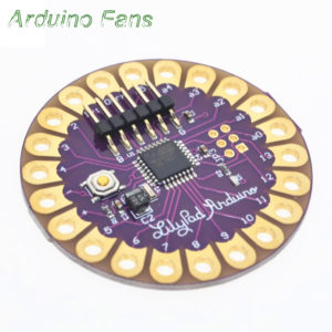 LilyPad 328 ATMega328P 16Mhz Wearable Arduino Development Board
₨ 429
LilyPad 328 ATMega328P 16Mhz Wearable Arduino Development Board
₨ 429
Reviews
There are no reviews yet.