
Learn how to build a compact Arduino Nano multimeter with a 0.91″ OLED display. Measure DC voltage up to 30V and resistance up to 1MΩ with ease
Build a compact Arduino Nano multimeter with a 0.91″ OLED display to measure voltage and resistance using I2C and a push button.
🔧 About the Project
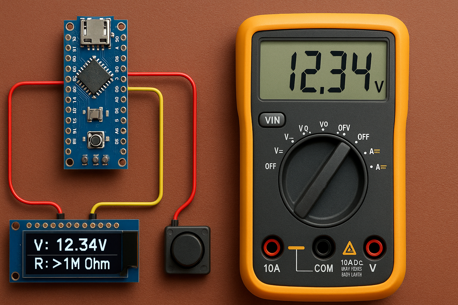
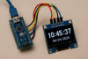
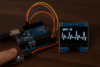
This project demonstrates how to build a compact digital multimeter using an Arduino Nano, a 0.91″ I2C OLED display (128×32), and a push button to switch modes. The multimeter can accurately measure DC voltage (0–30V) and resistance (0–1MΩ), displaying the readings clearly on a single-line OLED screen.
The voltmeter function uses a simple voltage divider circuit to safely scale down high voltages for Arduino’s ADC. The ohmmeter function uses a known resistor in a voltage divider to calculate the unknown resistance using the analog input. A button allows toggling between the two modes, making the device compact and versatile.
This is an ideal beginner-to-intermediate electronics project, perfect for learning:
- Analog signal reading
- I2C OLED interfacing
- Basic circuit design (voltage/resistance measurement)
- Mode toggling with debounced input
Whether you’re a hobbyist, student, or engineer, this project helps expand your understanding of Arduino-based instrumentation.
🛠️ Wiring Diagram
OLED 128×32 (SSD1306, I2C)
- VCC → 5V
- GND → GND
- SDA → A4
- SCL → A5
Button (Mode Toggle)
- One pin → D2
- Other pin → GND
- Pull-up enabled in code
Voltage Divider for 0–30V
- Vin → R1 (27kΩ) → Node
- Node → R2 (5.1kΩ) → GND
- Node → A0 (Arduino)
Ohmmeter
- 5V → Known Resistor (1kΩ) → Node
- Node → Unknown Resistor → GND
- Node → A1 (Arduino)
🔁 Modes
| Press Button | Switches between: |
|---|---|
| Mode 1 | Voltmeter |
| Mode 2 | Ohmmeter |
🔌 1. Measuring Voltage (0–30V DC)
🧠 Concept:
Arduino analog pins can only read up to 5V, so we use a voltage divider to scale higher voltages down.
⚡ Circuit:
Use two resistors:
- R1 = 27kΩ
- R2 = 5.1kΩ
Connect them like this:
(Vin) ----[ R1 ]----+----[ R2 ]---- GND
                   |
                 (A0)
🧮 Calculation:
The voltage at A0 is:
V_A0 = (R2 / (R1 + R2)) * Vin
Vin = V_A0 * ((R1 + R2) / R2)
✅ In Code:
float raw = analogRead(A0);
float v = (raw * 5.0 / 1023.0);        // A0 voltage
float vin = v * ((R1 + R2) / R2);      // Scaled up to real voltage
🔧 2. Measuring Resistance (0–1MΩ)
🧠 Concept:
Use a known resistor (Rknown) and measure voltage drop across the unknown resistor using a voltage divider.
⚡ Circuit:
5V ---[ Rknown ]---+---[ Runknown ]--- GND
                   |
                 (A1)
- Rknown = 1kΩ
- A1 measures the voltage between them
🧮 Formula:
V_A1 = Voltage at A1
Runknown = (5.0 * Rknown / V_A1) - Rknown
✅ In Code:
float raw = analogRead(A1);
float v = (raw * 5.0 / 1023.0);        // A1 voltage
float r = (5.0 * Rknown / v) - Rknown;
⚠️ Tips:
- Use 1% tolerance resistors for better accuracy
- Avoid touching components during resistance measurement
- Don’t measure resistance on a powered circuit
✅ Arduino Sketch
#include <Wire.h>
#include <Adafruit_GFX.h>
#include <Adafruit_SSD1306.h>

#define SCREEN_WIDTH 128
#define SCREEN_HEIGHT 32
#define OLED_RESET -1
Adafruit_SSD1306 display(SCREEN_WIDTH, SCREEN_HEIGHT, &Wire, OLED_RESET);

#define VOLT_PIN A0
#define OHM_PIN A1
#define BUTTON_PIN 2

// Voltage divider
const float R1 = 27000.0;
const float R2 = 5100.0;

// Known resistor for ohmmeter
const float knownResistor = 1000.0;

// Button debounce
unsigned long lastDebounceTime = 0;
unsigned long debounceDelay = 50;
bool lastButtonState = HIGH;
bool currentButtonState = HIGH;
int mode = 0;

void setup() {
  pinMode(BUTTON_PIN, INPUT_PULLUP);
  display.begin(SSD1306_SWITCHCAPVCC, 0x3C);
  display.clearDisplay();
  display.setTextColor(SSD1306_WHITE);
  display.setTextSize(1);
}

void loop() {
  handleButton();

  display.clearDisplay();
  if (mode == 0) {
    float voltage = readVoltage();
    display.setTextSize(2);
    display.setCursor(0, 0);
    display.print("V: ");
    display.print(voltage, 2);
    display.println("V");
  } else {
    float resistance = readResistance();
    display.setTextSize(2);
    display.setCursor(0, 0);
    display.print("R: ");
    if (resistance < 1e6) {
      display.print(resistance, 0);
      display.println(" Ohm");
    } else {
      display.println(">1M Ohm");
    }
  }
  display.display();
  delay(300);
}

void handleButton() {
  bool reading = digitalRead(BUTTON_PIN);
  if (reading != lastButtonState) {
    lastDebounceTime = millis();
  }

  if ((millis() - lastDebounceTime) > debounceDelay) {
    if (reading != currentButtonState) {
      currentButtonState = reading;
      if (currentButtonState == LOW) {
        mode = (mode + 1) % 2;
      }
    }
  }
  lastButtonState = reading;
}

float readVoltage() {
  int raw = analogRead(VOLT_PIN);
  float v = (raw * 5.0 / 1023.0);
  return v * ((R1 + R2) / R2);
}

float readResistance() {
  int raw = analogRead(OHM_PIN);
  float v = raw * 5.0 / 1023.0;

  if (v == 0) return 1e6; // Open circuit
  float unknownResistor = (5.0 * knownResistor / v) - knownResistor;
  return max(0.0, unknownResistor);
}
Learn to build a compact Arduino Nano multimeter with a 0.91″ OLED display—measure 0–30V and 0–1MΩ with I2C & a push button.
Step-by-step DIY: Arduino Nano + 128×32 OLED multimeter to measure voltage and resistance with I2C & mode-toggle button.
Build your own Arduino Nano voltmeter & ohmmeter with 0.91″ OLED display—perfect for electronics blogs and maker projects.
✅ Conclusion
This project shows how easy it is to turn an Arduino Nano and a 0.91″ OLED display into a simple yet effective digital multimeter. By combining voltage and resistance measurement with a push-button mode toggle, you’ve created a compact, useful tool for any electronics bench.
Whether you’re measuring 0–30V DC or checking resistors up to 1MΩ, this DIY multimeter is a practical introduction to analog sensing, I2C display control, and real-world circuit design. It’s affordable, educational, and easy to expand with features like data logging or auto-ranging.
Keep experimenting and enhancing it, your next project could be a full-featured handheld tester!
🚀 Share This Project!
If you found this DIY Arduino multimeter helpful, help others discover it too by sharing this project with your friends on social media sites.


