
Learn how to build a DIY Arduino fire alarm system using a flame sensor and temperature sensor. This step-by-step project includes a circuit diagram, code, and real-world applications, ideal for home safety or educational use.
Creating a basic fire alarm system using Arduino involves detecting fire (typically via temperature or flame sensors) and triggering an alarm like a buzzer or LED. Below is a complete example using a Flame Sensor and/or Temperature Sensor (e.g., LM35 or DHT11).
🔥 🔔 Usage of the Arduino Fire Alarm System Project
🏠 1. Home Fire Safety
- Detects early signs of fire through flame or high temperature.
- Alerts the residents via a buzzer and LED, helping them evacuate in time.
- Can be installed in kitchens, bedrooms, or living rooms.
🏢 2. Offices and Small Businesses
- Acts as a low-cost fire safety system for small offices or shops.
- Ideal for places without expensive commercial fire systems.
- Easy to expand using multiple sensors in different rooms.
🧪 3. Educational Purpose
- Great for learning Arduino and sensor integration.
- Teaches important concepts: digital vs. analog sensors, conditional logic, and alarms.
- Often used in school and college projects or science fairs.
🏭 4. Industrial or Workshop Monitoring
- Can be placed near electrical panels, soldering stations, or machines prone to overheating or sparks.
- Provides early detection before fire spreads.
🌐 5. Smart Home / IoT Integration (Optional)
- Can be expanded to send SMS, emails, or app notifications using modules like:
- ESP8266 (Wi-Fi)
- GSM module (SIM800L)
- Can be connected to home automation systems (e.g., Blynk, Home Assistant).
🚫 6. Fire Prevention
Can trigger fans, sprinklers, or cut power using relays in advanced setups.
Alerts before an actual fire breaks out (e.g., detecting a candle or match flame).
🔧 Components Needed:
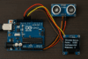
- Arduino Uno or compatible board
- Flame sensor
- DHT11 or LM35 temperature sensor
- Buzzer
- Red LED (for alarm indication)
- Resistors (220Ω for LED)
- Breadboard and jumper wires
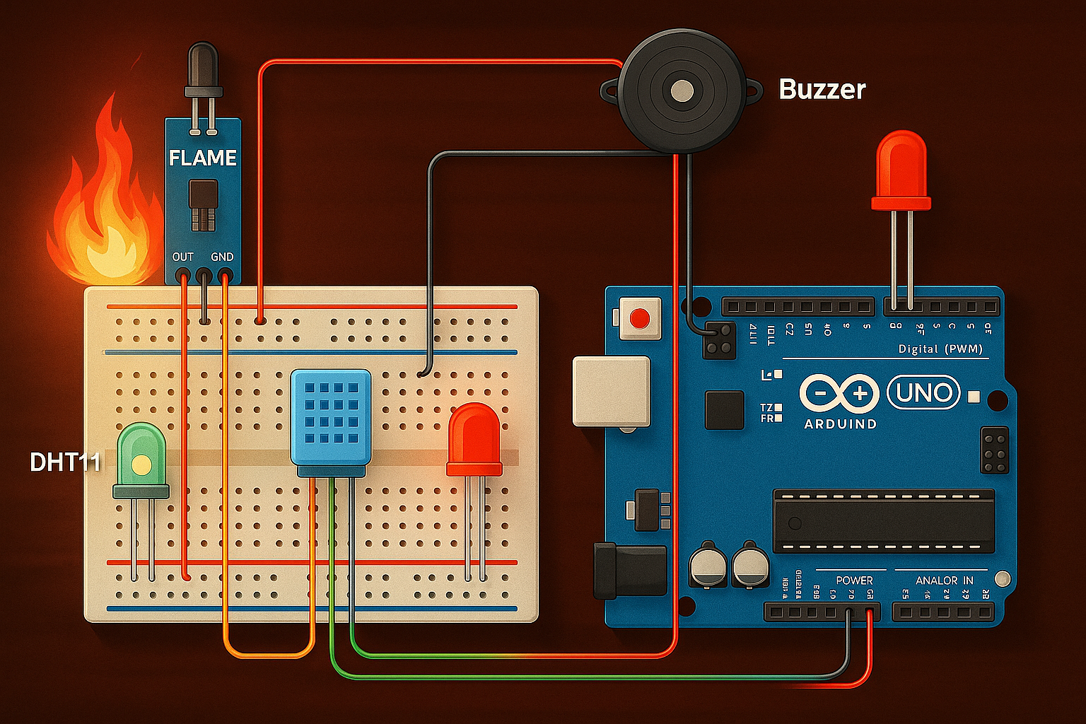
🔌 Circuit Connections
1. Flame Sensor
- VCC → 5V
- GND → GND
- D0 → Arduino pin 2
2. DHT11 Sensor (if used)
- VCC → 5V
- GND → GND
- Data → Arduino pin 3
(Use 10k pull-up resistor between VCC and Data pin)
3. Buzzer and LED
- Buzzer + → Arduino pin 8
- LED Anode → Arduino pin 9 (via 220Ω resistor)
- Buzzer – and LED Cathode → GND
📝 Notes:
- The flame sensor usually outputs LOW when flame is detected, hence
flameDetected == LOW. - Adjust the temperature threshold (e.g., 50°C) as needed.
- Optionally, you can add an LCD or Wi-Fi alert (e.g., via ESP8266) to notify remotely.
Here’s a step-by-step explanation of how the Arduino fire alarm system works:
🔍 1. Sensor Input
a. Flame Sensor
- Detects infrared light emitted by flames.
- Has a digital output (D0) that goes:
- LOW (0) when flame is detected
- HIGH (1) when no flame is present
b. Temperature Sensor (DHT11 or LM35)
- Measures ambient temperature.
- If the temperature is above a set limit (e.g., 50°C), it is considered a fire hazard.
⚙️ 2. Arduino Logic
Every second, the Arduino does the following:
- Reads the flame sensor pin (digitalRead):
- If it’s LOW → Flame is detected.
- Reads the temperature (via DHT11 or LM35):
- If temperature ≥ 50°C → Consider it as possible fire.
- Evaluates both conditions:
- If either flame is detected or temperature is too high,
- It activates the buzzer and LED alarm.
- Otherwise,
- Turns them OFF.
- If either flame is detected or temperature is too high,
🔔 3. Alarm Output
- Buzzer sounds continuously when fire is detected.
- Red LED blinks or stays on to visually indicate the alarm state.
📟 4. Serial Monitor Output (for Debugging)
- The Arduino prints temperature and flame detection status every second.
- e.g.,
Temp: 52.3 C | Flame: YES
- e.g.,
You can view this using the Serial Monitor in the Arduino IDE (set baud rate to 9600).
🔄 Summary Flow:
[Sensor Input]
   ↓
[Check: Flame Detected OR Temp ≥ 50°C]
   ↓
If TRUE:
   → Activate Buzzer & LED
Else:
   → Turn Off Buzzer & LED
🧠 Arduino Code
#include <DHT.h>

#define DHTPIN 3
#define DHTTYPE DHT11

#define FLAME_SENSOR_PIN 2
#define BUZZER_PIN 8
#define LED_PIN 9

DHT dht(DHTPIN, DHTTYPE);

void setup() {
  pinMode(FLAME_SENSOR_PIN, INPUT);
  pinMode(BUZZER_PIN, OUTPUT);
  pinMode(LED_PIN, OUTPUT);

  Serial.begin(9600);
  dht.begin();
}

void loop() {
  int flameDetected = digitalRead(FLAME_SENSOR_PIN);
  float temp = dht.readTemperature();

  Serial.print("Temp: ");
  Serial.print(temp);
  Serial.print(" C | Flame: ");
  Serial.println(flameDetected == LOW ? "YES" : "NO");

  if (flameDetected == LOW || temp >= 50.0) {
    // Fire alarm triggered
    digitalWrite(BUZZER_PIN, HIGH);
    digitalWrite(LED_PIN, HIGH);
  } else {
    digitalWrite(BUZZER_PIN, LOW);
    digitalWrite(LED_PIN, LOW);
  }

  delay(1000);
}
✅ Conclusion
This Arduino-based fire alarm system is a low-cost, easy-to-build, and effective solution for detecting early signs of fire using a flame sensor and temperature sensor. It demonstrates:
- Practical use of sensors for real-world safety applications
- Basic Arduino programming and logic control
- Real-time alerts via buzzer and LED when danger is detected
This project is ideal for:
- Home and small office fire safety
- Educational demonstrations
- A base model for more advanced IoT-based alarm systems
You can further enhance the system with:
- SMS/email alerts using GSM or ESP modules
- LCD display for real-time readings
- Integration with smart home platforms


