
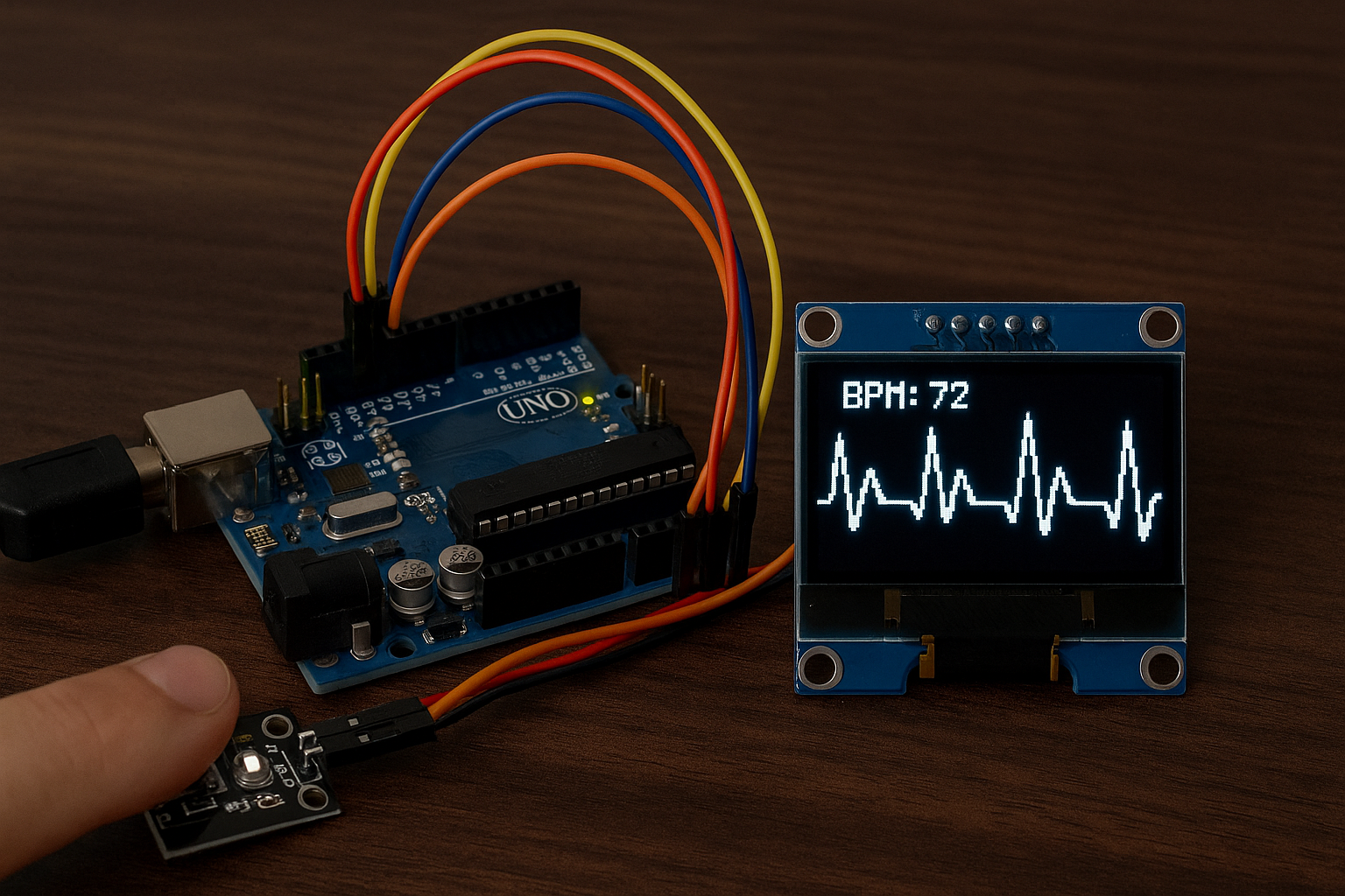
Monitor your heart rate in real-time using an Arduino-based heartbeat sensor and an OLED display. This DIY electronics project uses a pulse sensor (like KY-039 or Pulse Sensor) to detect your heartbeat and display both the BPM (beats per minute) and a live scrolling waveform on a compact SSD1306 OLED screen. Ideal for beginners and makers, this project combines health monitoring with embedded systems for an engaging and educational experience.
Here’s a simple Arduino project that uses a heartbeat sensor (like the KY-039 or Pulse Sensor) to measure heart rate and display it on an OLED screen (SSD1306 128×64 I2C).
🧰 Components Needed
- Arduino Uno / Nano / Mega
- Heartbeat sensor (KY-039 or Pulse Sensor)
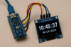
- OLED Display (SSD1306 128×64, I2C)
- Jumper wires
- Breadboard (optional)
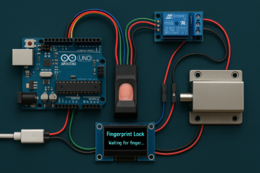
🔌 Wiring Diagram
For Pulse Sensor (3-pin: VCC, GND, Signal)
| Pulse Sensor | Arduino |
|---|---|
| VCC | 5V |
| GND | GND |
| Signal | A0 |
For OLED Display (I2C)
| OLED Pin | Arduino |
|---|---|
| VCC | 3.3V or 5V |
| GND | GND |
| SDA | A4 (Uno/Nano), 20 (Mega) |
| SCL | A5 (Uno/Nano), 21 (Mega) |
📟 Arduino Code
#include <Wire.h>
#include <Adafruit_GFX.h>
#include <Adafruit_SSD1306.h>

#define OLED_WIDTH 128
#define OLED_HEIGHT 64
#define OLED_RESET -1
Adafruit_SSD1306 display(OLED_WIDTH, OLED_HEIGHT, &Wire, OLED_RESET);

const int pulsePin = A0;
int pulseValue = 0;
unsigned long lastBeat = 0;
int BPM = 0;
int beatsPerMinute[10];
int beatIndex = 0;

void setup() {
  Serial.begin(9600);
  pinMode(pulsePin, INPUT);

  if (!display.begin(SSD1306_SWITCHCAPVCC, 0x3C)) {
    Serial.println("OLED not found");
    while (1);
  }

  display.clearDisplay();
  display.setTextSize(2);
  display.setTextColor(SSD1306_WHITE);
  display.setCursor(0, 10);
  display.println("Heartbeat");
  display.display();
  delay(1000);
}

void loop() {
  pulseValue = analogRead(pulsePin);
  static bool isBeating = false;

  if (pulseValue > 550 && !isBeating) {  // Threshold may need adjustment
    unsigned long currentTime = millis();
    int interval = currentTime - lastBeat;
    lastBeat = currentTime;

    BPM = 60000 / interval;
    beatsPerMinute[beatIndex++] = BPM;
    if (beatIndex >= 10) beatIndex = 0;

    isBeating = true;
    showBPM();
  }

  if (pulseValue < 500) {
    isBeating = false;
  }

  delay(10);  // sampling delay
}

void showBPM() {
  display.clearDisplay();
  display.setTextSize(1);
  display.setCursor(0, 0);
  display.print("Heartbeat Sensor");

  display.setTextSize(2);
  display.setCursor(0, 30);
  display.print("BPM: ");
  display.print(BPM);

  display.display();
}
📝 Notes
- Thresholds (
>550) may need adjustment depending on your sensor and lighting conditions. - For accurate readings, keep your finger still over the sensor.
- You can average the BPM from the
beatsPerMinute[]array for more stability.
Here’s an enhanced version of the Arduino heartbeat sensor project that plots a real-time pulse waveform on the OLED display, along with the current BPM.
🔁 How It Works
- Continuously samples analog values from the heartbeat sensor.
- Detects peaks to calculate BPM.
- Plots each sample as a vertical line to simulate a real-time pulse waveform.
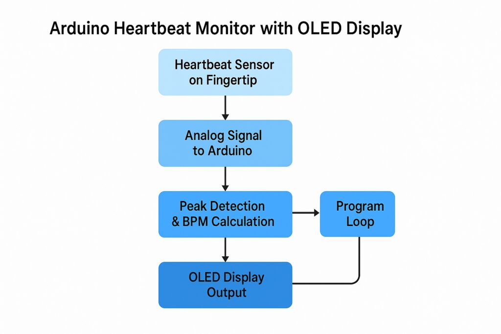
- Pulse Detection
A heartbeat sensor (e.g., KY-039 or Pulse Sensor) is placed on your fingertip. It detects slight changes in light intensity caused by blood flow during each heartbeat. - Analog Signal Reading
The sensor sends an analog signal to the Arduino. These voltage changes correspond to the pulse rhythm. - Peak Detection & BPM Calculation
The Arduino continuously reads the sensor data and identifies peaks (high points) that represent heartbeats. It calculates the time interval between peaks and converts it into BPM (beats per minute) using:BPM = 60000 / interval_in_milliseconds - OLED Display Output
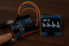
The SSD1306 OLED screen shows:- The current BPM value.
- A real-time scrolling waveform that represents the heartbeat rhythm visually.
- Looping Process
The program loops continuously, refreshing the display and updating BPM and waveform data in real time.
🛠️ Code: Heartbeat + Waveform on OLED
#include <Wire.h>
#include <Adafruit_GFX.h>
#include <Adafruit_SSD1306.h>

#define OLED_WIDTH 128
#define OLED_HEIGHT 64
#define OLED_RESET -1
Adafruit_SSD1306 display(OLED_WIDTH, OLED_HEIGHT, &Wire, OLED_RESET);

const int pulsePin = A0;
int pulseValue = 0;

unsigned long lastBeat = 0;
int BPM = 0;
bool isBeating = false;

int waveformX = 0;

void setup() {
  Serial.begin(9600);
  pinMode(pulsePin, INPUT);

  if (!display.begin(SSD1306_SWITCHCAPVCC, 0x3C)) {
    Serial.println("OLED not found");
    while (1);
  }

  display.clearDisplay();
  display.setTextSize(1);
  display.setTextColor(SSD1306_WHITE);
  display.setCursor(10, 10);
  display.println("Initializing...");
  display.display();
  delay(1000);
  display.clearDisplay();
}

void loop() {
  pulseValue = analogRead(pulsePin);

  // Peak detection for BPM
  if (pulseValue > 550 && !isBeating) {
    unsigned long currentTime = millis();
    int interval = currentTime - lastBeat;
    lastBeat = currentTime;

    BPM = 60000 / interval;
    isBeating = true;
  }

  if (pulseValue < 500) {
    isBeating = false;
  }

  drawWaveform(pulseValue);
  delay(10);
}

void drawWaveform(int value) {
  // Map pulse value (usually between 500-800) to OLED Y range
  int y = map(value, 500, 800, OLED_HEIGHT - 1, 0);  // Invert Y axis

  // Clear only the current vertical line column
  display.drawFastVLine(waveformX, 0, OLED_HEIGHT, BLACK);

  // Draw the new waveform line
  display.drawPixel(waveformX, y, WHITE);

  // Draw BPM text
  display.fillRect(0, 0, 60, 10, BLACK);
  display.setTextSize(1);
  display.setCursor(0, 0);
  display.print("BPM:");
  display.print(BPM);

  display.display();

  // Move to next X column
  waveformX++;
  if (waveformX >= OLED_WIDTH) {
    waveformX = 0;
    display.clearDisplay(); // full clear when we wrap around
  }
}
🧪 Output Example
- BPM is displayed in the top-left corner.
- Pulse waveform scrolls horizontally, line-by-line.
- When the waveform reaches the screen edge, it resets.
🔧 Tips
- If the waveform is off-screen or jittery, adjust the
map()range forvaluebased on your actual analogRead output. - Place finger firmly on the sensor, and test under consistent lighting for stability.
📢 Get Involved!
Liked this project? Here’s what you can do next:
- 💾 Get the full source code to start building.
- 🛠️ Try it Yourself – Gather the components and give this project a go!
- 💬 Leave a Comment – Have questions or improvements? Share your thoughts below.
- 🔁 Share This Post – Help other makers and students discover this project by sharing it on social media.
- 📬 Subscribe – Stay updated with more DIY electronics and Arduino tutorials.
🧾 Conclusion
Building an Arduino Heartbeat Monitor with an OLED Display is a rewarding DIY project that combines biometric sensing, real-time data visualization, and embedded programming. Whether you’re a beginner or an experienced maker, this project offers hands-on experience with analog sensors, OLED graphics, and signal processing. It’s a practical and educational way to explore how wearable health tech works right from your workbench.


